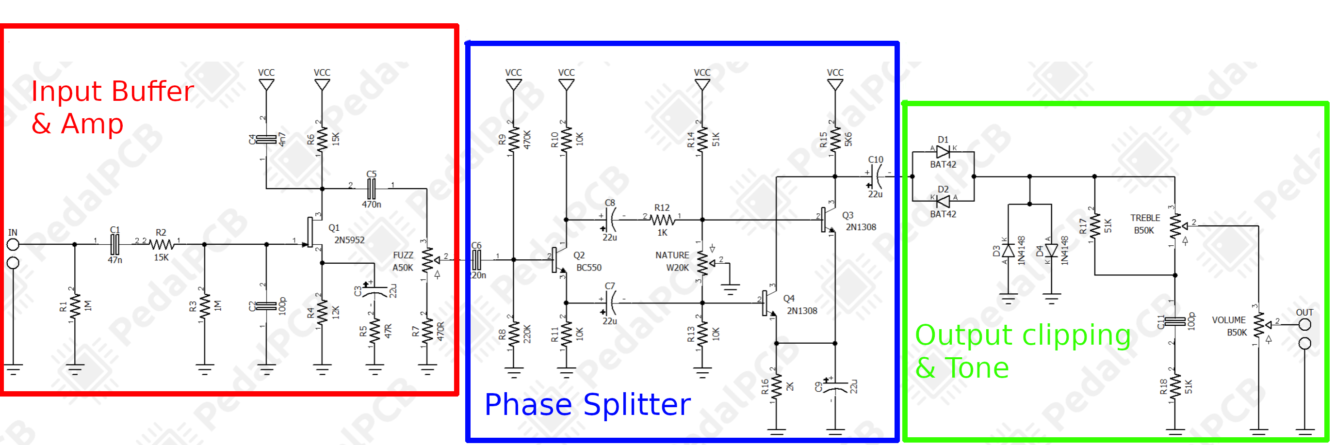
 I've divided the circuit into 3 pieces like this:
Not entirely sure why I decided to do an analysis on this pedal but it has some interesting traits to it. Having never played it myself this is all speculation on how I think these parts would interact but I'm fairly confident it's correct.
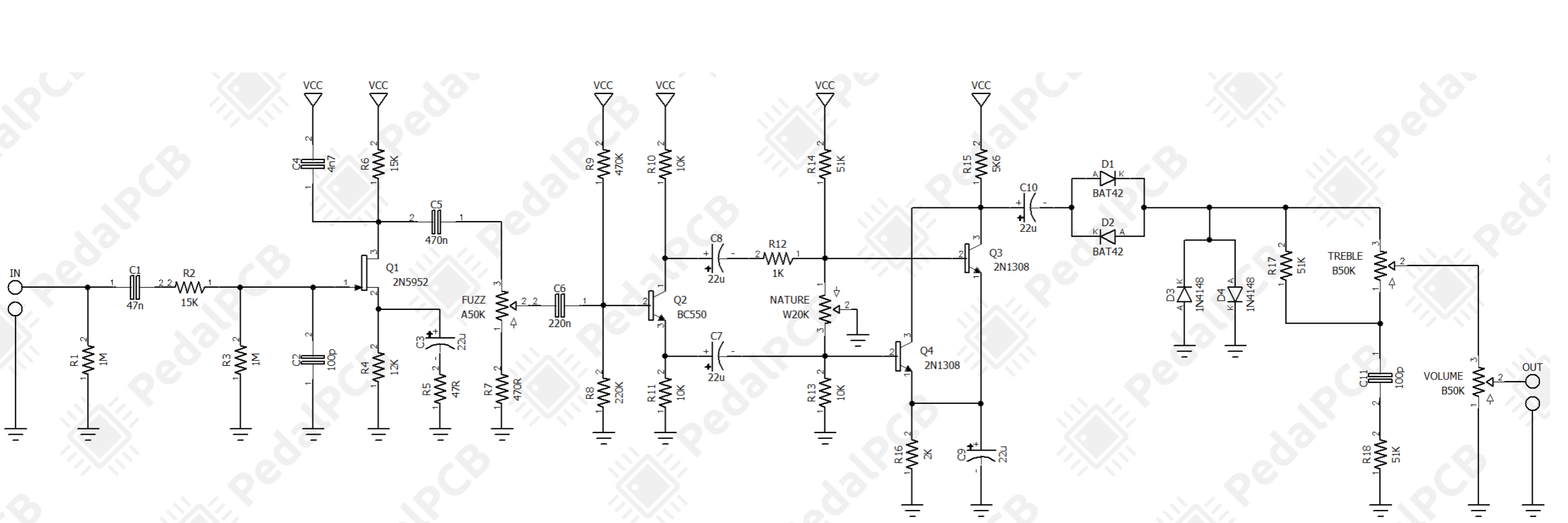
Here's the pedal schematic as shown in the pedalpcb build doc:
I've divided the circuit into 3 pieces like this:
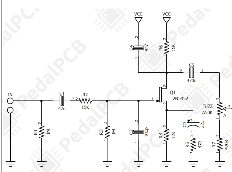
this configuration of a JFET with a pair of resistors (R4 & R6) and a capacitor (C3) is a common source inverting amplifier. JFETs can vary a lot but generally have good (high) input impedence making for a good input stage . Depending on the JFET used here there may be some gain and possibly some distortion as well. Discrete JFETs like this are getting increasingly hard to find so in a personal redesign I would probably setup a MOSFET common source amplifier. This would require a few changes (like a resistor biasing setup) but they're easier to come by and a lot less finicky. The output pulled from the drain has its bias removed with C5 and the 50k Fuzz potentiometer bleeds signal to ground. This acts as a fuzz control by cutting the incoming volume (possibly below the input). R7 puts a lower limit on this volume but it is extremely small. Choice of R7 would greatly change the setting's feel.
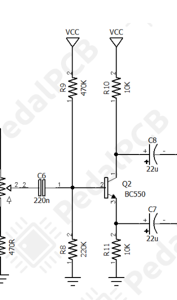
A BJT transistor setup like this where Re = Rc (R10 & R11 here) is called a phase splitter. The voltage measured at the collector will be 180deg out of phase from the input, the emitter voltage will be in phase.
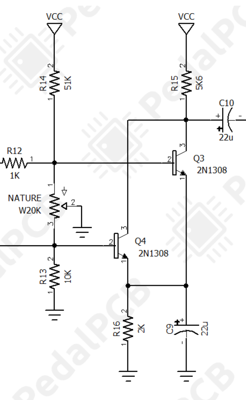
The upper inverted path is then biased by R14 and the 20k "Nature" pot. At the potentiometer midpoint ~10kOhms this places a voltage of about 1.5V which is perfectly adequate for most BJT transistors. The lower non-inverted path has ground potential across it and has no bias voltage. Turning the Nature knob does several things at once. Firstly, lowering the resistance to ground for the upper path creates a voltage divider with R12. This both lowers the amplitude of this path and causes the bias to dip. The other end of the pot is then increasing the resistance to ground for the non-inverted path. Turning the knob the other way lowers the non-inverted amplitude slightly but more importantly increases the gain of the inverting path. Lowering the resistance to ground for the emitter (through the capacitor) creates less negative feedback for the phase splitter. The BJT begins acting more like a common emitter amplifier. Since this path is specifically through C7 the gain won't mess with the bias of Q2 and should hopefully be less prone to oscillations.
Ignoring Q4 at first, Q3 then acts as a relatively high gain amplifier. At voltages less than ~600mV Q4 will remain in cutoff and do nothing. With these several gain stages the signal is significantly squared. At higher amplitude of the non-inverting path (with either a louder input or setting the Nature knob) can activate this transistor. When this happens the voltage at the shared collector resistor R15 gets pulled lower. Since this signal is 180deg out of phase though the voltage drop happens when the signal is swinging high. This creates a folded notch in the wave and an octave-fuzz style effect.
{Adjusting the Nature knob}
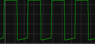
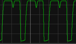
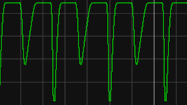
Notice the duty-cycle of this square wave changes greatly with the Nature knob as well. This changes the harmonic content and creates a very dynamic sounding fuzz.
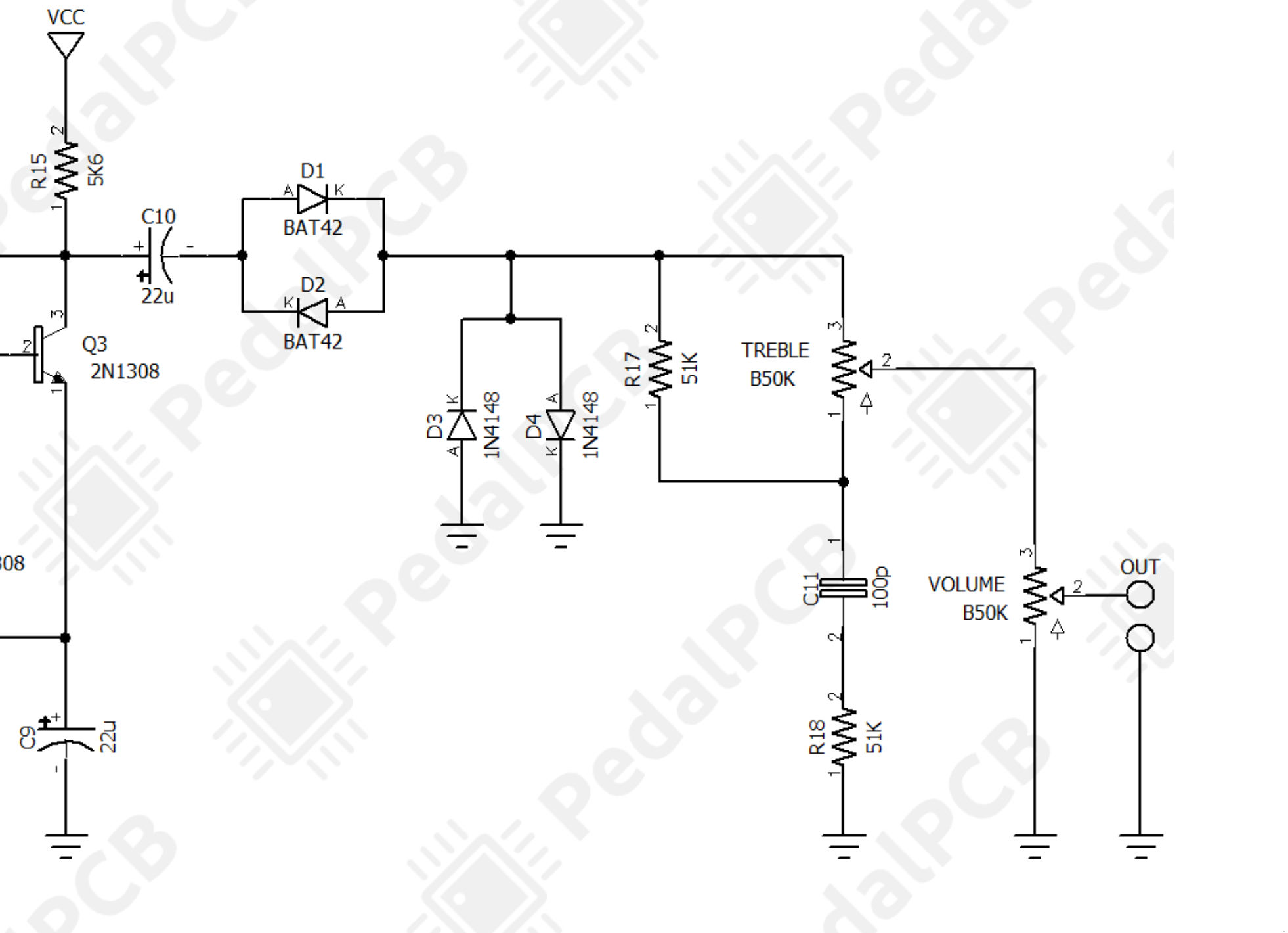
After a DC blocking capacitor C10, the signal goes into a pair of Schottkey diodes. According to the datasheet these have a forward voltage threshold of 0.4V-0.65V. Diodes arranged in series like this (as opposed to the other diodes) create whats known as crossover distortion. This sort of distortion is very harsh sounding (often considered to be what gives the Harmonic Percolator its sound). Smaller voltage Schottkey diodes are used here to allow lower amplitude signals. Higher thresholds like 1n4148s would remain closed too much and pass too little signal creating sputtering. Diodes D3 and D4 create more standard clipping. I can't imagine these were added for squaring since the transistor amplifiers did that just fine. Instead it's likely to create some compression over the very high gain (take it out and see what happens). I'm very confused by the choice in capacitor and resistor for the treble control. A 51k resistor and a 100pF capacitor rolls off frequencies over 31kHz which is at the border of human hearing. The other 51k resistor on the capacitor lessens This even more. Removing R18 and replacing C11 with a more reasonable 10nF capacitor gets a more reasonable 320Hz. The final volume knob is nothing noteworthy.